Tutorial: Materials
The Materials application illustrates how graphic materials can be used to add a bit of colour to our mesh.
This tutorial shows how to
- create standard materials
- create proprietary material
- create material with an image field
- apply material to a graphic
- use regions to separate parts of mesh
The souce code used in this tutorial is available from the physiome project svn server.
Overview
In visualising a mesh we often use colours to separate the different objects being viewed. One way to add colour to visualise a mesh in PyZinc is with graphic materials (often referred to as just materials). Graphic materials work in the same way as OpenGL materials, that is we set the diffuse, ambient, emission, shininess, and specular properties to achieve the colouring desired. PyZinc comes with a standard set of graphic materials, these are not defined automatically but can be created by calling defineStandardMaterials() from the graphics material module.
This tutorial also introduces regions and how they can be used to separate parts of a mesh. Regions are completely independent of each other (except when using the alias field) and thus enable us to have a high degree of independence from one region to another.
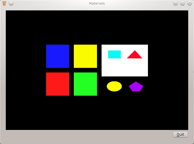
To see the effect of using materials we will create a simple 2D mesh in each region and visualise the mesh with a surface graphic. It is to the surface graphic that we apply the material to, to create the final visualisation.
Regions
The following code snippet creates five regions so that later we can have five 2D meshes which are independent of each other. We keep a handle to each region so we can iterate over the regions and create the required mesh. Here’s the code:
Line 4 here we create an attached region. That is the child has the default_region as a parent, we can also create unattached regions, move, and remove regions.
Standard Graphic Materials
To define the standard graphic materials we only need to call the appropriate API. The graphics module holds the graphics material module which defines a method defineStandardMaterials(). This method will define twelve graphic materials, here is the full list:
- black
- blue
- bone
- gray50
- gold
- green
- muscle
- red
- silver
- tissue
- transparent_gray50
- white
Once defined these graphic materials can be found with findMaterialByName() from the graphics material module object.
note:
If you create a graphic material and set its name to one used by a standard material. Your material will be replaced with the standard graphic material with the same name if you call defineStandardMaterials() after creating your graphic material.
Creating Graphic Materials
Creating a graphic material is very easy, here is how:
Line 19 creates a default graphic material from the graphics material module object. The default material is opaque white.
Line 20 we give the graphic material a name so that we may retrieve it later from the graphics module.
Line 21 we set the ‘managed’ attribute to true. This tells the graphics module to keep the material until the graphics module itself is being destroyed. Which alleviates us from holding a handle to the new material.
Lines 22 - 23 we set the appropriate attributes with an RGB triple to represent the colour.
The remaining attributes that have not been used in this tutorial are:
- ATTRIBUTE_ALPHA
- ATTRIBUTE_EMISSION
- ATTRIBUTE_SHININESS
- ATTRIBUTE_SPECULAR
The alpha attribute controls the alpha channel or the level of opacity of the material. For a full discussion of the other attributes read the section ‘Defining Material Properties’ in the OpenGl programming book, available online here
Creating Graphic Material Using an Image Field
We can use an image field in a graphic material to create an OpenGL texture. This is a very good way of visualising images, wether they are DICOMs, jpg, or png. Here is the code:
Lines 7 - 11 we create a graphic material from the graphics material module, assign it a name, and set the is managed attribute true.
Lines 13 - 36 we read in the desired image from disk using the stream information as seen in tutorial 2.
Line 38 we set the image field on the material and assign a texture buffer to use. The PyZinc library has four texture buffers for use numbered 1, 2, 3, and 4. Each texture buffer has the following purpose: 1 is for a texture; 2 is for a normal map; 3 is for a colour lookup; 4 is undefined/for future use
Applying Graphic Material to Graphic
Graphic materials created from the graphic material module are available anywhere in the region tree for any graphic to use. In each of our regions we create a 2D finite element and visualise it with a surface graphic. When we create the surface graphic we set the material for that surface to use. Here is the code:
Lines 7 - 10 we iterate over the regions that we kept a handle to and use an index to get a matching list of graphic material names.
Line 13 search the graphic module for the current graphic material name.
Line 22 set the material for the surface graphic to use.
Lines 23 - 25 if the graphic material is our ‘texture’ using the image field, we need to set a texture coordinate field. Here we use the xi field which will map the image size to the finite element size automatically.